This is an MCQ-quiz for ACT Science, which include questions on finding experimental design in physics.
Laura is performing an experiment with a 5kg weight tied to a 3m rope tied to the ceiling as shown:
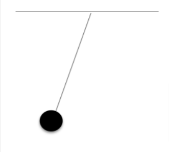
Laura drops the weight and allows it to swing freely. She measures how long it takes for the weight to return to it"s original position (assume no forces outside of gravity are acting upon the pendulum). This is also called one oscillation.
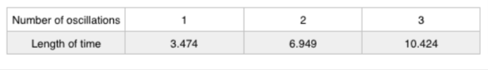
Experiment 1:
Laura created the following table for her first measurement of the pendulum"s oscillations.
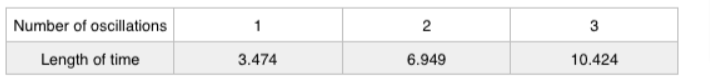
Experiment 2:
Laura performed the experiment again, this time using a 6kg weight.
Experiment 3:
Laura performed the experiment again, this time using a 3kg weight and a 5m rope.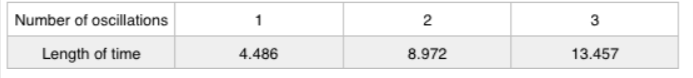
Jerry reads about this experiment, and attempts to recreate the experiment at home. He observes that when he lets go of the pendulum, it never reaches its original height. It gets close, but never fully reaches it. Why?
Jerry is using the wrong weight.
Jerry is using the wrong length of rope.
External forces acting on the pendulum.
Jerry did not tie the pendulum to the ceiling.
A student was interested in determining the relationship between the current, voltage, and resistance in a direct circuit, such as those exemplified by batteries connected to light bulbs. The student built the circuit presented in Figure 1 using a 2 ohm resistor.
Figure 1:
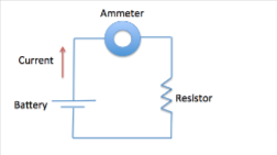
The current that flows through the circuit can be calculated using the equation , where is the voltage of the battery, is the current flowing through the circuit, and is the resistance of the resistor.
The student used a 2 ohm resistor and batteries of various voltages to obtain the results in Table 1. The currents shown in the table are NOT calculated using the formula , but instead directly measured from the circuit using an ammeter. It is important to note that the measured current will only exactly equal the calculated current if the system contains no internal resistance.
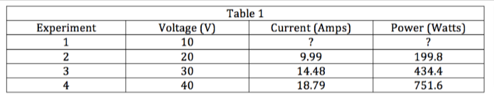
In Experiment 2, the student calculated the current to be 10 amps using the equation. However, when the student measured the current, it did not equal exactly 10 amps, but instead 9.99 amps. Which of the following is a possible explanation for the discrepancy?
None of the other answer choices
The system contains internal resistance.
The student calculated incorrectly.
The system contains external power.
A fiber-optic Michelson interferometer is a device that detects changes in optical paths. In a fiber-optic interferometer, a coherent light source (usually a laser) is sent through a beam splitter that splits the light along two paths. These beams are coupled into fiber optic cables that can be arranged and manipulated more freely than mirrors. The two beams are finally recombined by a second beam splitter and superimposed on a screen. If there is a phase difference between the two waves, interference fringes will be viewed on the screen.
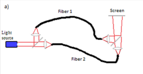
By observing fringe shifts, one can quantify the change in optical path difference between the two fibers using the following equation:
where m is the number of fringe shifts, x is the difference between the optical paths of the two beams, and is the change in the optical path difference.
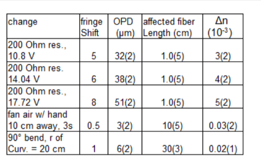
Experiment 1:
A student sets up a fiber-optic Michelson interferometer and heats one of the fibers with various resistors and power supplies, fans air over one of the fibers, and then bends one of the fibers. The resulting fringe shifts, as well as the change in optical path difference (OPD), are shown below.

In this experiment, the student used 632 nm light. For small changes in optical path difference, which wavelength of light would be the best?
800 nm
460 nm
1064 nm
632 nm
A fiber-optic Michelson interferometer is a device that detects changes in optical paths. In a fiber-optic interferometer, a coherent light source (usually a laser) is sent through a beam splitter that splits the light along two paths. These beams are coupled into fiber optic cables that can be arranged and manipulated more freely than mirrors. The two beams are finally recombined by a second beam splitter and superimposed on a screen. If there is a phase difference between the two waves, interference fringes will be viewed on the screen.

By observing fringe shifts, one can quantify the change in optical path difference between the two fibers using the following equation:
m=Δx/λ
where m is the number of fringe shifts, x is the difference between the optical paths of the two beams, and is the change in the optical path difference.
Experiment 1:
A student sets up a fiber-optic Michelson interferometer and heats one of the fibers with various resistors and power supplies, fans air over one of the fibers, and then bends one of the fibers. The resulting fringe shifts, as well as the change in optical path difference (OPD), are shown below.

The experiment is set up such that both beam paths have the same length. What would be the effect of doubling the path length for both of the beam paths?
There would be higher optical path difference.
There would be half as many fringe shifts.
There would be twice as many fringe shifts.
There would be no discernable effect on the number of fringe shifts.
A fiber-optic Michelson interferometer is a device that detects changes in optical paths. In a fiber-optic interferometer, a coherent light source (usually a laser) is sent through a beam splitter that splits the light along two paths. These beams are coupled into fiber optic cables that can be arranged and manipulated more freely than mirrors. The two beams are finally recombined by a second beam splitter and superimposed on a screen. If there is a phase difference between the two waves, interference fringes will be viewed on the screen.

By observing fringe shifts, one can quantify the change in optical path difference between the two fibers using the following equation:
m=Δx/λ
where m is the number of fringe shifts, x is the difference between the optical paths of the two beams, and is the change in the optical path difference.
Experiment 1:
A student sets up a fiber-optic Michelson interferometer and heats one of the fibers with various resistors and power supplies, fans air over one of the fibers, and then bends one of the fibers. The resulting fringe shifts, as well as the change in optical path difference (OPD), are shown below.

Suppose the student conducted the experiment with 632 nm light. What would happen to the measured fringe shifts if 1064 nm light were used instead?
The fringe shifts would be multiplied by 1.7.
The fringe shifts would be multiplied by 3.4
The fringe shifts would be divided by 1.7.
The fringe shifts would be divided by 3.4.
A fiber-optic Michelson interferometer is a device that detects changes in optical paths. In a fiber-optic interferometer, a coherent light source (usually a laser) is sent through a beam splitter that splits the light along two paths. These beams are coupled into fiber optic cables that can be arranged and manipulated more freely than mirrors. The two beams are finally recombined by a second beam splitter and superimposed on a screen. If there is a phase difference between the two waves, interference fringes will be viewed on the screen.

By observing fringe shifts, one can quantify the change in optical path difference between the two fibers using the following equation:
m=Δx/λ
where m is the number of fringe shifts, x is the difference between the optical paths of the two beams, and is the change in the optical path difference.
Experiment 1:
A student sets up a fiber-optic Michelson interferometer and heats one of the fibers with various resistors and power supplies, fans air over one of the fibers, and then bends one of the fibers. The resulting fringe shifts, as well as the change in optical path difference (OPD), are shown below.

One way optical fibers can contract and expand is through thermal changes. According to the data, what is the effect of increasing the voltage drop through a resistor?
The increased voltage leads to higher power dissipation.
The increased voltage leads to a greater decrease in the speed of light.
The increased voltage allows for more efficient electric transmission.
The increased voltage does not affect the experimental data.
A fiber-optic Michelson interferometer is a device that detects changes in optical paths. In a fiber-optic interferometer, a coherent light source (usually a laser) is sent through a beam splitter that splits the light along two paths. These beams are coupled into fiber optic cables that can be arranged and manipulated more freely than mirrors. The two beams are finally recombined by a second beam splitter and superimposed on a screen. If there is a phase difference between the two waves, interference fringes will be viewed on the screen.

By observing fringe shifts, one can quantify the change in optical path difference between the two fibers using the following equation:
m=Δx/λ
where m is the number of fringe shifts, x is the difference between the optical paths of the two beams, and is the change in the optical path difference.
Experiment 1:
A student sets up a fiber-optic Michelson interferometer and heats one of the fibers with various resistors and power supplies, fans air over one of the fibers, and then bends one of the fibers. The resulting fringe shifts, as well as the change in optical path difference (OPD), are shown below. Uncertainties are given in parentheses next to the measured values.

The optical path is related not only to the physical distance, but to the index of refraction of the medium.
The velocity of light in a medium with index of refraction is given by:
where is the speed of light in a vacuum.
Suppose the student measures a higher index of refraction for fiber 1 than for fiber 2.
What does this finding imply about the travel time of a photon passing through fiber 2?
The photon's transit time would depend on its initial velocity.
The photon would take the same time to reach the screen.
The photon would take a shorter time to reach the screen.
The photon would take a longer time to reach the screen.
A fiber-optic Michelson interferometer is a device that detects changes in optical paths. In a fiber-optic interferometer, a coherent light source (usually a laser) is sent through a beam splitter that splits the light along two paths. These beams are coupled into fiber optic cables that can be arranged and manipulated more freely than mirrors. The two beams are finally recombined by a second beam splitter and superimposed on a screen. If there is a phase difference between the two waves, interference fringes will be viewed on the screen.

By observing fringe shifts, one can quantify the change in optical path difference between the two fibers using the following equation:
m=Δx/λ
where m is the number of fringe shifts, x is the difference between the optical paths of the two beams, and is the change in the optical path difference.
Experiment 1:
A student sets up a fiber-optic Michelson interferometer and heats one of the fibers with various resistors and power supplies, fans air over one of the fibers, and then bends one of the fibers. The resulting fringe shifts, as well as the change in optical path difference (OPD), are shown below.

What is one valid hypothesis for why fanning the air near a fiber optic cable should cause 0.5 fringe shifts in the student"s experiment?
The air changes how the light is coupled into the fiber-optic cables by the lens.
The air cools or heats one of the fiber optic cables more than the other, causing it to shrink or expand.
The air's motion causes refraction of the beam, thereby distorting the interference pattern observed on the screen.
The air introduces disturbances into the optics of the light source, leading to diffraction patterns.
A fiber-optic Michelson interferometer is a device that detects changes in optical paths. In a fiber-optic interferometer, a coherent light source (usually a laser) is sent through a beam splitter that splits the light along two paths. These beams are coupled into fiber optic cables that can be arranged and manipulated more freely than mirrors. The two beams are finally recombined by a second beam splitter and superimposed on a screen. If there is a phase difference between the two waves, interference fringes will be viewed on the screen.

By observing fringe shifts, one can quantify the change in optical path difference between the two fibers using the following equation:
m=Δx/λ
where m is the number of fringe shifts, x is the difference between the optical paths of the two beams, and is the change in the optical path difference.
Experiment 1:
A student sets up a fiber-optic Michelson interferometer and heats one of the fibers with various resistors and power supplies, fans air over one of the fibers, and then bends one of the fibers. The resulting fringe shifts, as well as the change in optical path difference (OPD), are shown below.

Why would a standard halogen flashlight not be a good choice of light source in this experiment? Choose the answer that represents the greatest drawback.
The flashlight would cause excessive heating in the fiber cables.
The flashlight emits light waves that are not coherent.
The flashlight would reflect poorly off of the beam splitter.
The flashlight would not be visible on the screen after recombination.
A fiber-optic Michelson interferometer is a device that detects changes in optical paths. In a fiber-optic interferometer, a coherent light source (usually a laser) is sent through a beam splitter that splits the light along two paths. These beams are coupled into fiber optic cables that can be arranged and manipulated more freely than mirrors. The two beams are finally recombined by a second beam splitter and superimposed on a screen. If there is a phase difference between the two waves, interference fringes will be viewed on the screen.

By observing fringe shifts, one can quantify the change in optical path difference between the two fibers using the following equation:
m=Δx/λ
where m is the number of fringe shifts, x is the difference between the optical paths of the two beams, and is the change in the optical path difference.
Experiment 1:
A student sets up a fiber-optic Michelson interferometer and heats one of the fibers with various resistors and power supplies, fans air over one of the fibers, and then bends one of the fibers. The resulting fringe shifts, as well as the change in optical path difference (OPD), are shown below.
The experiment is repeated on a vehicle moving with a constant velocity at 100 mph. Why should we expect the data to remain the same?
According to the special theory of relativity, the speed of light is the same for an observer moving with constant velocity as it is for a stationary observer.
The extra length traveled by each light beam is offset by the reduced time spent at each location.
The motion of the vehicle exactly cancels out the speed of light.
The interference fringes themselves are affected by the motion of the screen due to the velocity of the vehicle.